mQ? What's That?We have all heard about the mQ valve... 
You should note that there is a spring between the poppet and the orifice plate, and the spring on the solenoid shaft that have been left out in this diagram. No matter how I did it, having them in there cluttered up the diagram, and made it very hard to understand how the pressure was working. They are there in real life, the diagram is not 100% accurate.
One of the missing springs fits between the poppet, and the orifice plate. This spring gives the poppet a push once the pressure has dropped on both sides of the poppet as the ball fires. The second spring sits around the solenoid shaft, pushing the shaft against the orifice plate. This creates the seal on the orifice plate when the system is at rest. Let's take the air pilot part first. In the case of most mechanical guns, the movement of the trigger releases the sear. That allows the hammer to be driven forward by the main spring, eventually hitting the valve stem, and opening the valve. On mechanical guns that have been upgraded to electronic frames, that linkage is still there, and is still being used. In the case of a cocker, an electronic solenoid is used to lower the sear, and thus replaces the mechanical movement of the trigger. The problem is you still have to create enough force on the sear to overcome the drag of the sear on the hammer lug. The stiffer the main spring is, the more force will be required, and the fewer shots you will get out of a battery. On the MQ, that mechanical linkage is removed completely. The sear solenoid, sear, sear spring, and the mechanical action of the hammer lug catching on the sear are all replaced by changing the pressure in the valve body it's self. This pressure change being used to move things is called an air pilot. When the air pilot activates, it uses a small amount of electricity from the battery to power the solenoid. The solenoid shaft is then pulled away from the orifice plate, allowing it to vent the pressure in the rear of the poppet. Now, since the pressure being vented already wants out, there is much less power needed to compress the spring around the solenoid shaft. The solenoid doesn't have to compress the spring by it's self, the pressure is already pushing against it, and helping to open the seal. By only using a small solenoid, and having the pressure do most of the work, the mQ saves battery life in a big way. Think of it this way: The air pilot is like a three way valve on a mechanical cocker. It only takes a little energy to move it, but you are changing the pressure balance in the system, and allowing the system to do the work for you. Now, the weird part, the balanced piston.... OK, let's forget about the MQ for a minute, and look at a plain old cocker ram. You put pressure into one side, and the shaft moves out. You empty the one side, and pressurize the other side, and the shaft moves in. That is what is used to cock, and load our guns. So, what happens in you put pressure on both sides at the same time? Logic would say the ram shaft would go to the middle of the travel, and stop there. Well, logic may say that, but a simple test says logic is wrong. The surface of the ram's piston has different working surfaces on each side, because of the ram shafts end is outside of the ram, the air pressure can't use it to generate force. Pressure can only create force when it is working against a surface. The more surface something has, the greater force any set pressure will be able to create. The more pressure applied, the more force generated on that surface. 
 On the left-hand side, there is 100 SI pushing against a surface of 1/2 inch square. On the right hand side, there is a pressure of 50 PSI pushing against a surface of 1". To figure out the force generated by a certain pressure against a certain surface, just multiply the pressure in PSI by the surface area in square inches.
In both cases, it comes out to 50lbs of force being created, so the piston will sit in the middle if both sides are pressurized at the same time.
So, what does all of this have to do with the MQ?
Simple, the poppet in the mQ is a balance piston. Air pressure is applied to both sides of the poppet, and the difference in the surface area forces the valve to seal. Now that you know how each part of the system works, here is how they both work together: The parts listed do the following jobs:
Valve Body: Holds the poppet, seals against the body of the gun, and the orifice plate. Poppet: Seals against the valve body, and moves to allow air into the bolt to fire the ball. Poppet Spring: Provides force to push the poppet closed after the pressure has dropped from behind it. Orifice Plate: Seals the back of the valve body, provides a small diameter air passage for the solenoid to seal. Solenoid Body: Holds the solenoid, allows pressure to vent from the rear of the valve body. Solenoid Core: Seals the back of the orifice plate, moves to allow air to vent from the read of the valve body Solenoid Core Spring: By pushing the solenoid core against the orifice plate, it creates the seal while the valve is at rest. Spacer: Holds everything in, and provides the force needed to seal the valve body to the gun body. 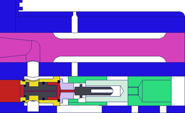 You can see that the front of the poppet seals off the valve chamber form the air passage to the bolt, but it also allows pressure through the center, and into the chamber on the other side of the poppet. That is what creates the different surface areas that are used to hold the valve closed. The surface of the poppet on the back end is larger than the sealing surface on the front, so the back creates more force with the same amount of pressure, pushing the valve closed to seal it. MQ at rest: The seal created by the solenoid shaft is held only by the spring that isn't in the diagram. Because the port in the orifice plate is so small, there is very little surface area for the pressure to work against, so it is relatively easy to hold this seal closed. 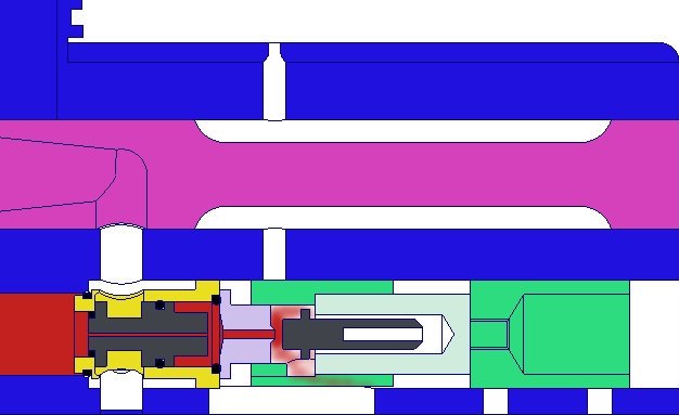 Here the solenoid has pulled the shaft back, compressing the spring on the solenoid shaft, breaking the seal against the orifice plate. That allows pressure behind the piston to vent. By allowing that pressure to vent, the balance between the front and the back of the piston is changed. This lowers the force holding the poppet closed, and allowing the pressure on the front of the poppet to push it back, while at the same time compressing the spring between the poppet and the orifice face. 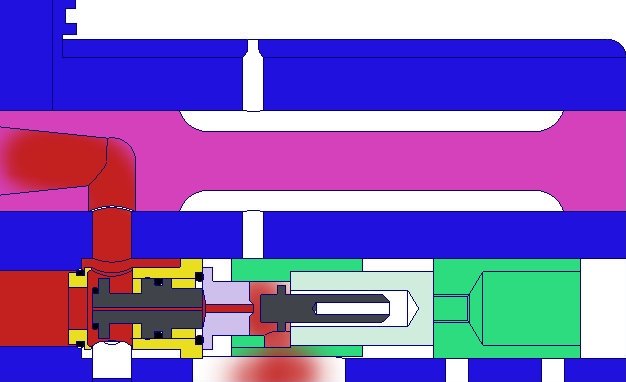 The pressure from the back of the piston has been bled out, allowing it to move completely back, and fully open the valve to the bolt. At this point, the ball is being fired. The pressure that was behind the piston is vented down, through the frame, where the sear used to be. 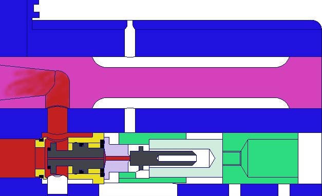 Here we can see that the solenoid shaft has been pushed forward by the spring, thus returned to the forward position, recreating the seal at the back of the poppet. This allows pressure to start building behind the poppet so it can be forced closed by a combination of the spring between the poppet and the orifice plate, and the air pressure. The poppet is returned to the forward position, sealing off the passage to the bolt, and putting the system back to it's resting state, ready for the next shot.  |
Your IP Address is: 3.12.153.79
Copyright © 2024 Moody Paintball.